Six short guides covering the decisions that shape a BBU project: bridge capacity, ride-through time, parallel architecture, heat, protocols and the certification path. Written for data-center engineers, not for brochures.
Each guide is short on purpose: the decision, the numbers that drive it, and the traps that show up at commissioning.
Start from measured rack draw, not nameplate. Bridge energy is load in kW times target minutes; compare it against usable capacity per module — 5.12 kWh for VB-5125, 1.5 kWh per node for VB-E3.
The right target comes from what happens after the bridge: generator start, UPS pickup or a controlled workload migration. VB-E3 anchors the short end — at least 5 minutes at full load, about 20 minutes at quarter load.
VB-5125 parallels up to 15 units per bus over CAN. The BMS balances charge and discharge current across the group and isolates any unit that drifts out of bounds.
LFP rewards moderation. VB-5125 charges from 0 to 55 °C and discharges from -20 to 60 °C; VB-E3 lives inside the server loop with cold-plate cooling, specified from -5 to 45 °C.
CAN 2.0B runs the bank, RS485 Modbus reaches BMS and EMS layers, SNMP feeds DCIM, and VB-E3 adds PMBus for in-server telemetry. Pick per layer, not per project fashion.
Each market wants specific, correctly worded claims: cells UN 38.3 tested, packs designed and tested to IEC 62619, a UL 1973 certification path for North America, CE marked with DoC for the EU.
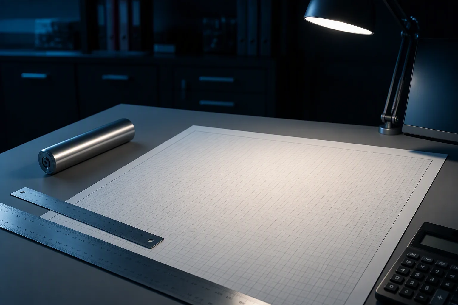
The guides follow the sequence of a real project: size the load, set the ride-through target, design the bank — then solve heat, communications and compliance before they solve you. Each pairs with a deeper page when you need the detail.
FIG.G3 — Planning desk: guides assume a measured load profile and a target migration window
A first-pass map from rack draw to a BBU configuration. Indicative only — final sizing is confirmed against your measured load profile.
| Load profile | Bridge target | Recommended configuration |
|---|---|---|
| Single AI node, up to 1.5 kW | 5 min at full load / 20 min at quarter load | VB-E3, one per node |
| Mixed rack, up to 5 kW | 30 to 60 min ride-through | 1 x VB-5125 (5.12 kWh) |
| Mixed rack, 10 to 15 kW | 45 to 90 min ride-through | 4 x VB-5125 (20.5 kWh) |
| AI rack, 30 to 60 kW (industry-estimated class) | Minutes-class bridge to genset | 6 to 12 x VB-5125 on one bus |
| ±400VDC bay, 80 kW-class | Rack-level ride-through | VB-H400 bays, paralleled to bay level |
| Outside these bands | Anything custom | Send the load profile — we size it with you |
FIG.G4 — Indicative configurations; runtime depends on temperature, depth of discharge and cell aging

Send rack power, bridge target and destination market. We return a sizing note, a configuration and a lead time — usually within 48 hours, always in writing.

Tell us your rack architecture and bridge-time target. Engineering reply within 48 hours, sample units available for qualified projects.
VB-5125 · VB-E3 · VB-H400
Fields marked * are required. Your details stay confidential.