A battery backup unit is only as good as its bridge, its battery management, and its cells. Three pages explain how VoltBridge handles each — from the sub-millisecond transfer to the 21700 LFP platform behind every shelf.
Each pillar has its own engineering page — diagrams, timing details and datasheet-grade tables included.
Grid loss to battery in under 1 ms, then a managed hand-off to genset or rectifier — the migration window your operations team actually plans around.
CAN 2.0B, RS485 Modbus and SNMP on the rack side, PMBus in the node; cell-level voltage and temperature with 0.5% SOC estimation.
3.2V cylindrical LFP cells with high-rate discharge, a ≥6,000-cycle platform rating and a -20~60°C discharge window.
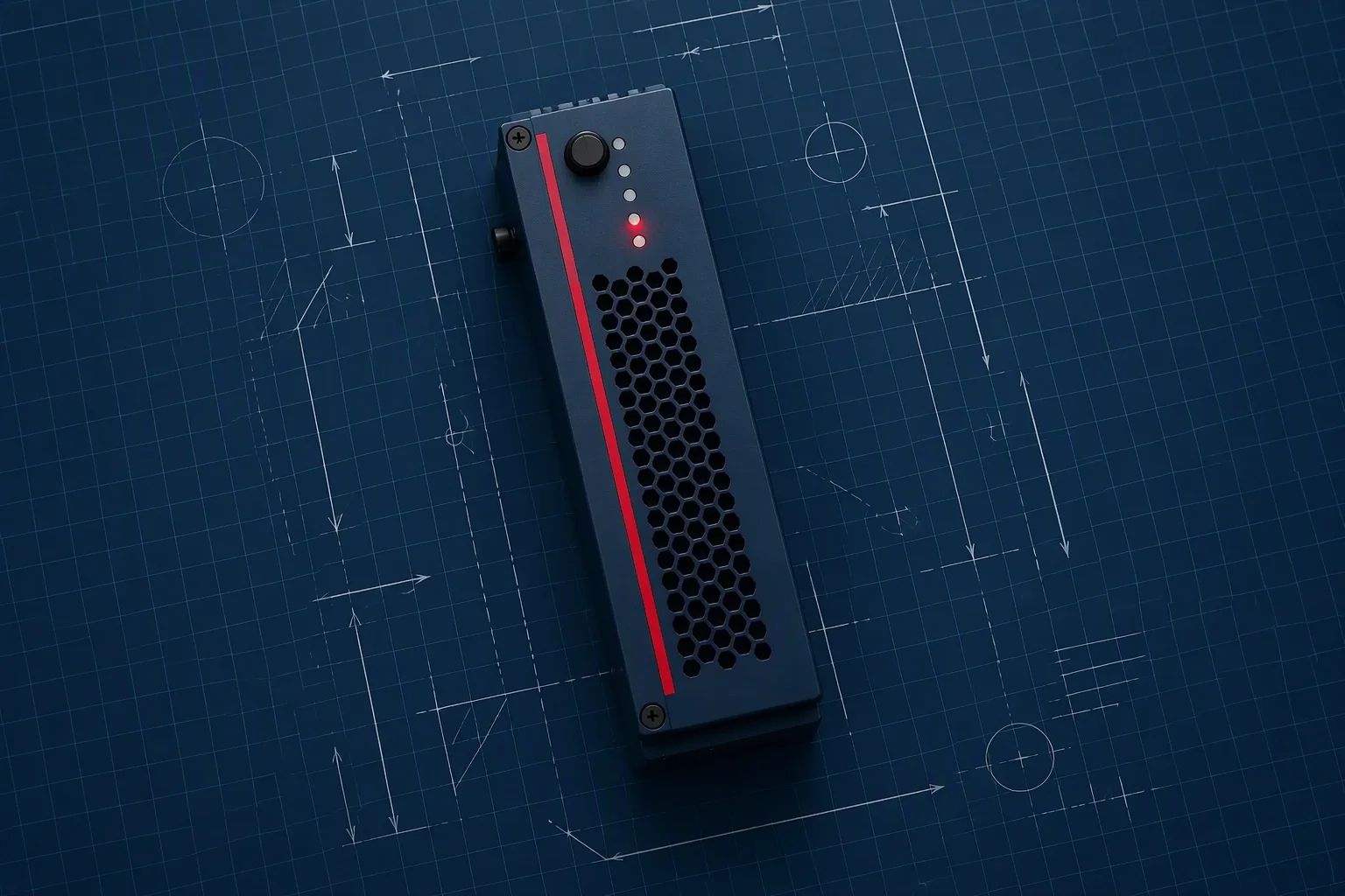
FIG.04 — Bridge architecture concept · 1536x1024
When grid power drops, the BBU closes onto the DC bus before downstream equipment notices. The node keeps computing through the gap; when the generator or rectifier plant picks up, the bridge hands the bus back and recharges. That controlled interval is the migration window — and every VoltBridge runtime claim is sized against it.
Hot-swap shelves and slot-in modules: capacity grows and failed units get replaced from the front of the row, not from behind it.
Cells are UN 38.3 tested, hardware is designed and tested to IEC 62619, and the CE DoC is carried consistently across every form factor.
Cell-level sensing below, SNMP and PMBus above — the battery reports to whichever management plane owns the rack.

Bridge timing, SOC accuracy, cell sourcing — our engineers answer technical RFQs directly, within 48 hours.

Tell us your rack architecture and bridge-time target. Engineering reply within 48 hours, sample units available for qualified projects.
VB-5125 · VB-E3 · VB-H400
Fields marked * are required. Your details stay confidential.